While a dynamometer is a great tool for sorting out engine combinations, there are those instances where some of the data provided conflicts with other data also being recorded. A case in point here is where the EGT’s (exhaust gas temperature) do not match up with the results of the oxygen sensors. Typically when dynoing an engine it’s either the EGT’s or the oxygen sensors being used to adjust the air/fuel ratio but not both. But having the capability to do both on the DTS dyno, it’s a nice plus to have all the data possible when doing these tests. Most of the time the different sets of data do help to collaborate each other. It’s when those data sets do not agree with each other is when the real questions arise.
Upon converting the 2010 Engine Masters Challenge Ford Y-Block engine from a street engine to a race engine for my 23T altered roadster, the disparity in readings between the EGT’s and oxygen sensors came to the forefront. At the time, it was a head scratcher. Although the EMC engine made respectable horsepower numbers in its new configuration as a race engine, I felt that it fell short of expectations when taking into full consideration the increase in compression ratio and using the longer duration camshaft. Late evening brain storming sessions with racers and other engine builders had them suggesting that the engine was too large for the cylinder head flow and the heads were simply not supporting the additional cubic inches. I saw this to some degree on the 403” Y that was built with the iron heads but was having a hard time buying this for the 375” Y combination using the ported Mummert aluminum heads.
But after plenty of time and much thought, I came to lean towards the idea that the exhaust system was over-scavenging. Said another way, there was an excess of intake charge going into the headers during the valve overlap cycle and there was a portion of the intake charge essentially being wasted. This assumption was based on that disparity between the EGT and oxygen sensor readings. The EGT’s were running on the cool side while the oxygen sensors were saying ‘spot on’ in regards to the fuel mixture. The spark plug readings were agreeing with the oxygen sensors while leaning and richening the fuel mixture based on the A/F readings was also agreeing with the power output numbers.
When the opportunity arose to build a similar engine for a customer, this was a perfect opportunity to validate the ‘over-scavenging’ theory and see if that was indeed where some lost power was hiding. With that in mind, a 375” Y engine with the same compression ratio and similarly ported aluminum heads is assembled. Two major engineering changes do take place in this engine and both changes are designed to reduce the amount of intake charge that’s lost during the overlap cycle. The connecting rod length is shortened 0.450” (from 6.750” to 6.300”) which reduces the amount of dwell time the piston sees at TDC. The other change is the camshaft lobe centerline angle which is increased from 108° to 112°; this reduces the number of crankshaft degrees that both the intake and exhaust valves are open together. These two changes reduce the amount of intake charge that can be lost out the exhaust when the headers are working at their optimum. The camshaft, other than the number of degrees on the lobe centerline angle, has the same specs as the one used on the revamped or racing version of the 2010 EMC engine.
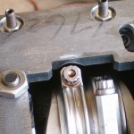
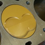
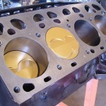
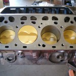
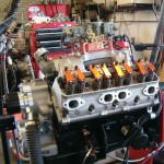
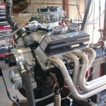
The remainder of this new 375” engine is as follows. The well seasoned C2AE-C 292 block has a November 1966 casting date and is finished bored to 3.859”. The crankshaft is billet steel by Moldex using stock 292 main sizes but 1.889” sized Honda rod journals instead of the factory 2.188” sized journals. The stroke is 4.000” and the Honda rod journal sizing helps to minimize any connecting rod to camshaft clearance issues that can become prevalent when doing stroker builds on the Ford Y-Block engines. The cylinder heads are Mummert aluminum and are ported by Joe D. Craine. Because the Mummert aluminum intakes were unavailable at the time of this particular engine build, a Blue Thunder intake was utilized and is also ported by Joe Craine. The static compression ratio is 13.56:1 and gets there using Diamond 9cc domed pistons that are ceramic coated on the domes and have a friction coating on the skirts. The top and 2nd groove piston rings are 1.2mm while the oil ring is a standard tension 3.0mm unit. Using the 1.2mm rings not only reduces the amount of ring surface area against the cylinder wall, they also have a reduced radial tension due to the radial thickness (inward width) being less than the older and more conventional ring sets. The connecting rods are out of the box 6.300” long Eagle’s utilizing a 0.927” pin and a Honda 1.889” rod journal. While a main bearing support girdle is used to strengthen the bottom end, an Innovators West damper helps to keep unwanted crankshaft harmonics to a minimum.
Click on pictures for larger images
Nothing fancy about the oiling system on this engine. The oiling system within the block itself remains basically as delivered from Ford with the exception of a machined groove in the center cam journal behind the cam bearing. This particular modification insures an adequate flow of oil to the rocker arm assemblies without worrying about the softer cam bearing material pressing itself into the center cam journal groove and restricting the flow at that point. Two extra holes are drilled into the oil filter adapter plate to insure a sufficient flow of oil into the filter in the higher rpm ranges. The original Ford engineers likely had no idea that these engines would eventually be running repeatedly in excess of 7000 rpms and actually staying together. A rebuilt Ford aluminum gerotor oil pump keeps the oil moving while a front sump oil pan seals up the bottom of the engine. The standard volume oil pumps as supplied by Ford still work well in this application.
Click on pictures for larger images
The valve train centers around an Iskenderian camshaft with a 296° advertised duration and 263° duration at 0.050” lifter rise on both the intake and exhaust lobes. As previously mentioned, the lobe centers are ground on 112°. The cam is installed at 110° intake lobe centerline or 2° advanced while U.S. manufactured Hylift Johnson lifters are the lifter of choice for this combination. A Rollmaster timing set (made in Australia) keeps the cam spinning in a set of Durabond cam bearings while Harland Sharp 1.6:1 roller tipped aluminum rockers pushes the net valve lift to 0.603”. Isky beehive valve springs and Isky retainers are used to keep the valves in their respective places. Due to the increase in valve spring pressure, pressurized oiling is used at the rockers thus eliminating the overflow tubes. The pushrods are by Smith Brothers and have an 8.000” effective length.
Engine break-in on the dyno was a non-event. The prerequisite twenty minutes at 2000-2600 rpms is used for cam break-in and during this time period, the dyno is repeatedly loaded and unloaded so that the engine sees ~100 HP at each dyno loading. This puts enough heat into the piston rings to do a very quick seating of the rings to the cylinder walls. For this engine, the customer provides Joe Gibbs 30W break-in oil while a Wix 51515R oil filter takes care of the filtration. No additional additives are used. I’ll add at this point that too much zinc/phosphate in the oil can cause ‘zinc overloading’ which is known to speed up pitting of the cam lobes. Once break-in is complete, the valve lash is checked and it’s verified that the valve train is holding up just fine. After the lash is adjusted to 0.016” hot for both the intake and exhaust valves, the engine is allowed to completely cool down to put a completed heat cycle into the valve springs. This single step greatly prolongs valve spring life. I’ll add that the valve lash with aluminum heads sees a 0.004” growth from cold to hot. If doing an initial cold lash setting on aluminum heads, then set the valves ~0.004” less than what you want when they are hot. This will get you in the ball park for the hot lash setting.
The first item on the agenda once testing commenced was to determine what the engine likes for ignition timing. The distributor chores are taken care of with a #8383 MSD distributor and a set of MSD carbon core wires. The black bushing supplied as an extra with the distributor is being used in conjunction with the light blue and light silver springs to provide an ignition advance curve that’s both short and all in by 3000 rpms. With the Autolite #3923 spark plugs gapped at 0.035”, the engine shows a definite preference for 37° total timing. Simply resetting the timing 1° above and below this causes a 6 & 7 HP drop depending upon which way you go. Going 2° away from 37° simply drops the power numbers even more. So 37° BTDC it is.
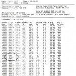
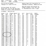
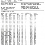
Once testing is completed, the engine is a solid 581+ HP performer. Three different carburetors were used during this testing session. While a 750 HP series vacuum secondary Holley (List #80529-1) makes 581 HP, a Quick Fuel 750 also with vac secondaries does slightly better at 582 HP. But when a 1050 cfm Dominator Holley (List #8896-2) is tried on the engine with an adapter, the power level jumps up to 585 HP and that’s with this particular carb still on the lean side. The torque values with the Dominator carb are also stout. Because this engine is leaving the shop with the Quick Fuel carb on it, no further testing is done with the Dominator carb which leaves some higher HP numbers on the table. Likely wouldn’t be 600 HP but would be crowding the 590 HP value.
So there you have it; a recipe for some serious Y horsepower. Following this article are the dyno sheets with the various carbs. That’s all for now and until next time, happy Y motoring. Ted Eaton.
750 Holley carb 750 QFT carb 1050 Holley
This article was originally published in The Y-Block Magazine, Issue #113, Nov-Dec 2012, Vol 19, No.6

