Y-Blocks would appear to have garnered a reputation for marking their territory when sitting still and so one of the most often asked questions is how to stop those pesky oil leaks at the rear of the engine. Because most of these are in the area of the rear main oil seal, I’ll go through the steps I take to insure that the back end of the engine is buttoned up securely during the rebuild thereby minimizing any oil leaks from this area. Because I use the rubber or neoprene rear main seals exclusively in those Y buildups that I do, I’ll only go into detail on using these seals and not the ‘rope’ style of seal. While neoprene seals are available from several gasket manufacturers for the 272/292 engines, only Best Gasket offers a made to fit neoprene rear seal for the larger mained 312 engine.
Best Gasket and Fel Pro rear seal kits….
Oil leaks at the back of the Y can likely be from one of several locations. These include the rear main seal itself, the side seals on the seal retainer, the oil pan bolts, the oil galley plugs, the cam plug, and residuals seeping down from the top and back of the engine. And let’s not forget the oil pump as it can also be a contributor but this particular leak is easier to spot than most. The key here is to get these areas sealed up during the initial engine assembly so they are not a problem once the engine is in the vehicle and running.
The oil galley plugs at the back of the block are 3/8” NPT (National Pipe Thread) and will require a nominal amount of sealer on the threads. For sealer, Permatex #2, a thin film of RTV, ‘high tack’, or teflon tape can be used. The key here is that some form of sealer must be used in lieu of simply relying on a dry fit of the tapered thread design of the screw in plugs being used.
The cam plug at the back of the block is typically installed at the machine shop but does need some form of sealer on it during installation. Installing it dry just increases the chances for an oil leak in that area.
Before installing the rear seal half into the block and laying the crankshaft into the bearings, check the seal groove depth both in the block and the rear seal retainer. It’s been passed along that the groove depth on a particular 312 block was deeper than normal which made the rear seal fit too low in the groove. Another instance was the groove depth in a 272 block being too shallow. Both cases were problems when it came to neoprene seal installation in these particular engines. To check this, simply lay the neoprene seal firmly in the upper and lower grooves with the neoprene seal ends level with where the cap fits the block and insure that the seal ends are flush with the block or edge of the cap. If the seal ends are lower than the block or edge of the seal retainer, then it’s either the incorrect seal for the application or a seal groove that’s too deep. If the seal half sits considerably higher at the block than normal when firmly putting it in the groove, then the possibility exists that the groove is too shallow or the incorrect seal for the application. These may be cases where a rope seal must be used.
The crankshaft journal diameter for the seals for the 239, 256, 272, and 292 engines is 2.625″ while the journal seal diameter for the 312 engine is 2.750″. Because of this there are two different neoprene seals available for these engines. Trying to use a 292 neoprene seal kit in a 312 engine will redefine what a rear seal leak really is as the seal ends will have a gapping hole in them.
Assuming the block being used has passed the groove depth test, a rear seal half will need to be laid into its groove at the back of the block before laying the crankshaft into the bearings. The lip of the seal “must” be facing forward or towards the inside of the engine. While no sealer is used on the outside diameter of the rear main seal before installing it in the block or the retaining cap, coating the outer edge of the seal halves with white grease can help to seal any small imperfections within the groove or seal that might be an oil leak otherwise. At this point, the seal half being laid into the block will need to be offset at the main journal parting line by about 1/4″-3/8”. This allows the retaining cap to self align so that the seal ends can actually butt to each other. Be sure that the lips on the seals are lubed prior to installing the crankshaft as installing dry can cause premature seal wear. A small amount of KW Copper Coat sealer is put on the block where the rear seal retainer fits. This will take care of any seepage that can potentially occur between the retainer and the the block mating surface. Take care not to put any sealer on the neoprene seal itself.
Offsetting the rear seal halves.
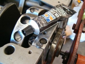
After the crankshaft has been laid into the bearings and the main caps torqued to specification, the rear seal retainer can then be readied for installation. KW Copper Coat or similar type of sealer is applied to the retainer flats where it mates to the block. At this point, the remaining rear seal half is laid into the retainer groove with emphasis being put on insuring that the lip of the seal faces the inside of the engine when the retainer is bolted in place. The offset in the seal where it sticks up on one side of the retainer will also need to match the offset of the seal half that’s already in the block. Again, use no sealer on the backside of the seal that installs in the rear seal retainer groove.
Sealer on bottom of retainer…..
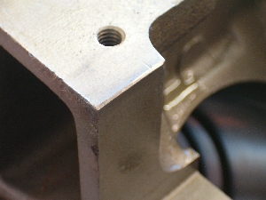
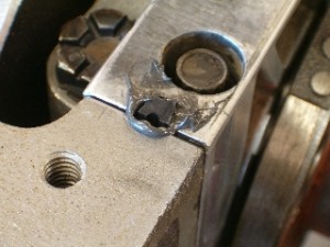
Before actually installing the seal retainer in the block, it must be determined which side seal design is being used as this will have a bearing on when the retainer itself is installed. If using the Best Gasket brand orange seals which are both soft and compressible, then the side seals and retainer are installed together as a unit into the block. If using the black rubber seals that uses ‘nails’ or small diameter rods, then the retainer is installed into the block without the side seals first being in place. Regardless of which seal design is being used, the leading edge of the block where the retainer starts being fitted into place should have the edge ‘broken’ with a file to facilitate the side seals starting in at this point easier. It’s desirable that the filing of this edge took place before final block cleaning to reduce the risk of metal filings within the new engine.
Chamfer detail…..
When using the Best Gasket orange side seals, the outside surfaces of the seals or the faces of the seals that contact the block are lightly oiled. A small dab of RTV on the end of the seals is also of a benefit in insuring that there is not a gap for oil seepage at the block and where the seal retainer itself mates to it. With a pair of long bolts or studs inserted both into the seal retainer retention bolt holes in the block and the seal retainer itself, the seal retainer is pushed into place while putting inward pressure on the side seals to insure that they stay in place while the retainer slides into place. With the retainer fully seated, the side seals are expected to be either flush or slightly below the pan rail surface. If the side seals protrude above the pan rail surface, then the seal retainer will need to be pulled back out and reinstalled to insure adequate insertion of the side seals. Torque the real seal retainer to 23-28 ft-lbs when satisfied with the side seal fit.
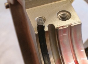
The use of the black rubber seals with their accompanying ‘nails’ presents a slightly different scenario. The retainer with the installed rear seal half and aforementioned KW Copper Coat application is installed into the block without the side seals in place. Torque the rear seal retainer to 23-28 ft-lbs.
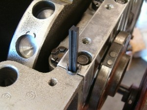
Before inserting the black side seals, put a small amount of RTV into each of the side seal holes. This RTV will be pushed down and ahead of the seals to insure a solid and leak free seal at the mating surface of the block where the side seals reside at the main journal parting line. At this point, install the side seals into the holes and push or tap them down until the seals bottom out. It may be necessary to grind a small bevel or chamfer on the leading edge of the rubber seals to facilitate starting them in their holes. The nails are then installed on the retainer side of the side seals and are simply tapped into place with a small hammer. Installing the nails on the block side of the side seals will almost guaranatee an oil leak so take due diligence in insuring that the nails are on the retainer side of the seals. As a side note, if an excess of RTV is used in the holes, it may be pushed out the front and rear sides of the retainer as the side seals are being pushed into place. This excess should be allowed to thoroughly dry before trimming or cutting off the excess amounts so it is flush with the block and/or retainer.
A small dab of RTV seals the deal….
And a quick note on the oil pumps. There are two styles of pumps and subsequently two methods employed in their manufacture to minimize oil leakage between the oil pump housing and the plate that covers the gears. The spur-gear style of pump incorporates a very thin paper gasket while the gerotor style of pump uses a rubber ‘O’ ring. In either of these, it’s important that due diligence be applied when servicing either style of oil pump to insure that all surfaces are clean and flat. New gaskets and/or ‘O’ rings are a prerequisite. Using a sequential and even tightening sequence when fastening the pump to the block with its related gasket is also recommended.
When it comes to oil leaks on the Y-Block family of engines, another often overlooked detail is the two oil pan bolts that locate into the rear oil seal retainer. These two threaded holes are open to the crankcase and are prone to leakage around the oil pan bolts if sealer is not used on the threads. Ideally, it’s best to use the factory supplied studs at this location but a fair number of these engines have had these studs removed over the course of time. When reinstalling the studs, be sure to use some form of thread sealer where the stud goes into the retainer. If just using pan bolts at this location, then use a small amount of RTV or other suitable sealer on the threads.
And here’s a word of caution with using RTV. Use only enough to get the job done regardless of where it’s being used. Excessive amounts of RTV can be pushed into the inside of the engine and if dislodged and in a worst case situation, can make its way into and through the oil pump where it can eventually plug or stop up an oil galley in the block or crankshaft.
While these are not the only approved steps or methods available for sealing up the back of these engines, these are the steps that I’ve found to have a very high success rate. A special thanks goes to Bill Phelps in Dallas Texas for prompting me to jump this article ahead of the others that are forthcoming.
Until next time, Ted Eaton.
Originally published in the Y-Block Magazine, Jul-Aug 2008 issue, Issue #87, Vol 15, No.4


