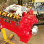
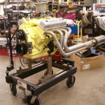
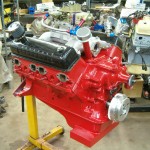
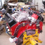
I recently had the opportunity to assemble a pair of Ford Y-Block engines that were very similar to each other and then dyno test each. Both engines had the same bore and stroke, the same camshaft grind, and the final static compression ratio (SCR) on each was very similar. The main differences were in the cylinder heads and intake manifolds. While one engine was slated for use in a standard transmission equipped ’54 Ford car for both street driving and some spirited road racing, the other was to be used in a ’56 Ford pickup as a daily driver with air conditioning and an automatic transmission. The road race engine is using ported oem iron ‘G’ heads while a set of Mummert aluminum heads are used on the daily driver pickup engine.
Each engine required a camshaft that would be very drivable in stop and go traffic. For this, the same part number Iskenderian camshafts are used with the duration at 0.050” being 228°/238° on the intakes & exhausts respectively. The advertised duration is 260°/272° while the lift at the valves with 1.6 rockers is .477”/.512”. The split duration format is being used for a variety of reasons including the use of full exhaust systems, better low rpm intake manifold vacuum, and improved torque characteristics in the lower rpm band. The camshafts are ground on 110° lobe centers and both are installed 3° advanced or at 107° intake lobe centerline.
Rollmaster timing sets are used and also common to both engines are Harland Sharp 1.6:1 roller tipped rockers. MSD p/n #8383 MSD billet distributors are responsible for routing the fire to the spark plugs. Both blocks have a machined groove added behind the center cam bearing to alleviate the potential for any future top end oiling problems. Two extra 5/16” holes are added to the oil filter plates to insure adequate flow capacity from the oil pump to the oil filter. Other than this pair of modifications, the block oiling systems remain virtually as delivered from Ford. The aluminum rocker arms are using pressurized oil with the factory overflow tubes being eliminated. Rocker to shaft clearance is set at 0.002”.
Both engines use 312 crankshafts where the main journals are reground to a standard 292 size. The rear seal journals are also reground to the 292 sizes while retaining the rear main seal crankshaft oil slingers. The rod journals are offset ground to a 3.580” stroke utilizing 2.000” journals. Because both crankshafts had been previously reground undersize, the maximum amount of stroke that would normally be available with standard size rod journal cranks was not available. The connecting rods are manufactured by Eagle and incorporate 6.125” center to center lengths. While the pickup engine uses a rebuilt factory style harmonic damper, the car engine uses one of the new Innovators West harmonic dampers. Both engines have some overbalance added to the crankshafts during the balancing procedure.
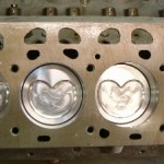
The bore sizes are 3.832” and the wrist pin compression height on the pistons is also the same being 1.830”. The piston tops do vary though due to the differences inthe combustion chambers on the cylinder heads being used. Because both engines are being targeted to use readily available 91-93 octane premium pump gasoline, the dynamic compression ratio (DCR) is being limited to 8.0:1. That meant to use the Mummert aluminum cylinder heads, the piston for that combination would require a 8cc dish netting a final static compression ratio of 9.7:1. The pistons for the iron headed engine would be a conventional flat top piston and would end up being 9.5:1 for the SCR. The selected piston rings for both engines are manufactured by Total Seal and and are conventional in design while being 1.5mm for the top and second grooves and 3.0mm for the oil ring.
Click on pictures for larger images
The iron headed engine for the 1954 Ford uses a pair of ‘posted’ ECZ-G cylinder heads. These had hardened exhaust seats suitable for unleaded fuels installed before going to the porting table. Along with the new stock diameter valves, Isky beehive valve springs and retainers are also installed. The closed valve spring pressure is 130 lbs while over the nose or open pressure is 295 lbs. Final combustion chamber volumes after milling are 68.9cc. This set of heads would use a Mummert aluminum single four barrel intake.
The Mummert aluminum heads for the 1956 Ford pickup are stock out of the box pieces utilizing the ‘as supplied’ valve springs and hardware. The closed spring pressure is 110 lbs while open pressure is 300 lbs. The intake manifold for this engine would be an older model Blue Thunder single four barrel intake. There was no need for the heat riser passage in the intake to be blocked off due to the heat passages in the heads not being opened up. ARP 7/16” head bolts are used to fasten the heads to the block on both engines.
Before decking the blocks, the steam holes were drilled, tapped and plugged. Because neither set of heads has steam holes and both vehicles have high radiator fill points, the steam holes in the block are not required. Plugging the holes also helps to strengthen the blocks in that area.
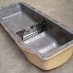
The oil pans do vary on each engine but simply due to the differences in the vehicles in which they are going in. The ’54 car uses a front sump pan that is modified for additional oil capacity while the ’56 pickup uses a rear sump pan that has had a gate put into it to stop the forward slosh of the oil during braking. The oil pumps for both engines are rebuilt gerotor pumps. These were chosen over new casting spur gear pumps as the georotor design has fewer cavitation issues along with less heat transfer into the oil itself. There are enough differences in oil pump design for its own article which is being saved for later.
The engines are started up using a full complement of Valvoline 10W-40 oil and Wix oil filters. No extra additives are used as this particular oil has the required levels of zinc & phosphate (ZDDP) for the older flat tappet camshafts. The camshafts and lifters however were thoroughly lubed with the Isky supplied molybdenum lube during the engine assembly which takes care of the initial lubrication requirements during startup. While the camshaft is being broken in, the water brake on the dyno is repeatedly loaded and unloaded so that the piston rings can be seated in during the same time frame. Once this operation has been completed, the engines are allowed to thoroughly cool to help put a completed heat cycle into the valve springs. This single operation significantly prolongs the life of the valve springs versus going straight into dyno pulls without a cooling cycle.
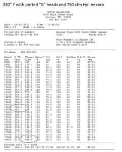
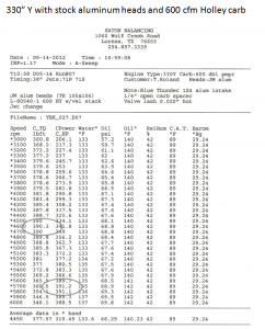
Both engines were started up with a known ‘good’ carburetor and in this case it’s a 750 cfm vacuum secondary Holley. The road race engine does gets a 600 cfm vacuum secondary Holley that’s heavily modified by lieu of the rules for one of the racing venues requiring nothing larger than a rated 600 cfm carburetor. That 600 carb actually outperforms the 750 carb in this rare case on both ends of the rpm scale and that is in part attributed to the superior work that was done to the carb metering circuits rather than the rated cfm difference. The aluminum headed engine had a 600 cfm double pumper carb available for testing and while it had excellent lowend dyno numbers, the 750 carb had better higher rpm numbers.
Click on pictures for larger images
The differences in power output between the two engines primarily rests with the cylinder heads. The ported iron heads peaked at 361 HP while the stock out of the box aluminum heads peaked at 404 HP. I’ve included dyno sheets for both engines and in this particular instance also supply sheets showing the performance differences between the carbs that were used. As a general rule, the smaller sized carbs will help low end torque values while the larger sized carbs help topend horsepower. As with any generalized rules, there are exceptions.
All for now and until next time, happy Y motoring. Ted Eaton.
Click on images for larger pictures.
Originally published in Y-Block Magazine, Issue #111, Jul-Aug 2012, Vol 19, No.4

